Scalability and Performance of Mobius® iFlex Bioreactors
Biopharmaceutical manufacturers need to produce a high-quality drug supply while reducing facility footprint and manufacturing costs. Intensified fed-batch and perfusion processes leveraging single-use bioreactors enable manufacturers to meet these requirements and at the same time, increase manufacturing flexibility and product yields.
Mobius® iFlex Bioreactors are single-use, stirred tank systems designed to support traditional and intensified fed-batch as well as perfusion cell culture applications. Several performance attributes and scalability data for these bioreactors are described below. The full Mobius® iFlex Bioreactors Scalability and Performance Guide can be accessed here.
Read more about
Geometric Scalability of Mobius® iFlex Bioreactors
The design of a bioreactor vessel impacts mixing, gas mass transfer rate, power per volume, and heat transfer. To simplify scaling of upstream bioprocesses from pilot to commercial operations with the Mobius® iFlex Bioreactors, vessel and component geometries were maintained across all sizes. Table 1 summarizes the design characteristics of Mobius® iFlex Bioreactors which range in working volumes from 15 L to 2000 L.
The Mobius® iFlex Bioreactor vessels were designed with a constant 2:1 aspect ratio, which compares the vessel height to diameter geometry (H:D). In addition, the bioreactors have high turndown ratios, which dictates the minimum working volume at each vessel scale. This increases flexibility and reduces the number of vessels needed in a single process, thus reducing facility footprint.
Impeller, Baffle, and Mixing Performance
Power Density
The power per unit volume (W/m3) describes the energy transfer from mechanical mixing into the cell culture medium in the bioreactor. Effective scale-up to 2000 L is highly dependent on a constant power density per system as it enables homogeneous mixing and optimized mass transfer.
The impeller power number (Np) is used to calculate power density at different scales. The power number is a proportionality constant between the rotational velocity of an impeller and the amount of energy it imparts into the mixing fluid and should be constant across systems for scalability. The number is unique to the impeller, motor, and vessel designs, and can be impacted by baffles and their proximity to walls within the vessel.
As shown in Figure 1, Mobius® iFlex Bioreactor impellers were designed to maintain a constant power number across all system sizes for scalable power input, mixing, and mass transfer performance.
Power Curves, Full Volume
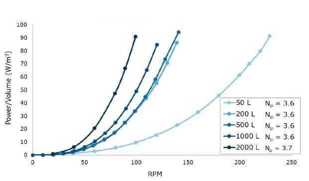
Figure 1.Power per unit volume (W/m3) curves for a range of impeller revolutions per minute (RPMs) at 50 L to 2000 L scales in representative acrylic tanks.
Tip Speed and Shear Rate
Tip speed, an important parameter associated with shear, was calculated based on the maximum RPM required to reach 100 W/m3 at each scale up to 2000 L (Figure 2). Multiple impeller iterations were evaluated to determine a final design where the target power number (Np) could be reached while maintaining less than or equal to 2.2 m/s tip speed at a maximum power density of 100 W/m3. Achieving these design criteria with the Mobius® iFlex Bioreactor helps to support cross system scalability and reduce the risk of shear associated with agitation.
Tip Speed, Full Volume
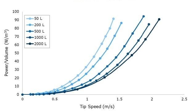
Figure 2.Power per unit volume (W/m3) curves at a range of impeller tip speeds for 50 L to 2000 L scales. Data is shown at full volume for n=1 runs averaging at least n=20 drive current points per RPM.
Mixing Time
To assess mixing performance of the Mobius® iFlex Bioreactors, experiments were conducted at maximum working volumes and at power densities ranging from 10-100 W/m3 in representative acrylic tanks. Optimized methods of determining mixing times were compared by commonly used sensor and colorimetric mixing methods.
A pH sensor mixing method was used to determine mixing times (Figure 3). At the start of the experiment, pH was adjusted to 4.0 using DI water and HCl. Two pH probes were placed in the tank and response curves were recorded following addition of concentrated acid or base. At the 50 L scale, a single pH probe was used due to space constraints in the acrylic system. Solutions of 5M NaOH and HCl were alternatively added to the center of the tank once stability was reached at a ratio of 1 mL per 25 L of solution. Mixing time was defined as the time for the pH profile to reach 99% of the final resting value at each agitation rate tested. For all Mobius® iFlex Bioreactor sizes, mixing times less than 34 seconds can be achieved at a full working volume and 100 W/m3.
pH Mixing Time, Full Volume
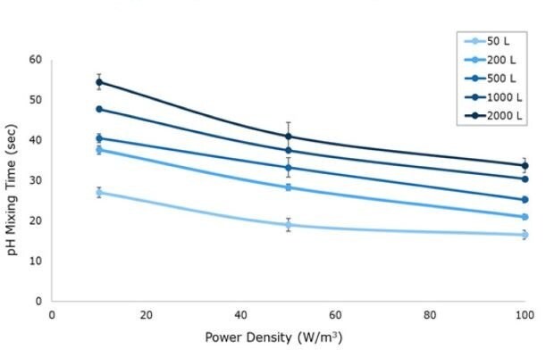
Figure 3.pH mixing time for 10, 50 and 100 W/m3 power input respective to vessel size from 50 L to 2000 L in representative acrylic tanks.
Volumetric Mass Transfer
Efficient gas transfer is essential for cell growth, metabolism, and protein production. Volumetric mass transfer (kLa) is an important output to understand mass transfer capacity in relation to viable cell densities (VCD).
The static gassing out method was used to determine kLa. Sensors were calibrated to 100% dissolved oxygen (DO) when fully saturated with air. The system was then purged with nitrogen until the sensor reached <2% DO, and air sparged into the system until the sensor plateaued at the saturated DO level.
The kLa value for each trial was calculated from a DO vs. time graph. To avoid sensor-related noise in determining the kLa, the calculation was based on DO concentrations between 10% to 90% of measured air saturation. The kLa values represent the slope of the line created by plotting the equation ln((C*-C1)/(C*-C)) = kLa*(t-t1) versus time (t2-t1).
For the Mobius® iFlex 200 L Bioreactor, kLa values between 1 and 100 hr-1 can be achieved at a 200 L working volume combining different mixing and sparging conditions; kLa values up to 80 hr-1 can be achieved at a 40 L working volume (Figure 4). For the Mobius® iFlex 2000 L Bioreactor, kLa values up to 72 hr-1 can be achieved at 2000 L working volume and kLa values up to 109 hr-1 can be achieved at 400 L working volume (see full guide for more details).

Figure 4.kLa results for high performance, drilled-hole and open pipe spargers with increasing air flowrates at 200 L scale for (top row) maximum 200 L and (bottom row) minimum 40 L working volume at 20 and 100 W/m3.
CO2 Stripping
Maintaining CO2 levels in the bioreactor through sparging and stripping is critical to control pH. At larger scales, CO2 can accumulate more rapidly due to the increased bubble residence time, and this requires effective stripping capabilities to remove excess CO2.
To assess the Mobius® iFlex bioreactor stripping capabilities, two DO and two CO2 probes were attached to the system via the sensor ports for data collection. As with the kLa studies, the static gassing out method was used to determine a kLa for air sparged into a CO2 saturated solution. CO2 was sparged into the system until saturation reached <10% DO. Air was then introduced via the open pipe or drilled-hole sparger until the solution reached <5% CO2 and >90% DO.
CO2 removal rate was calculated in percent per hour between 10% and 5% CO2, a typical working range for cell culture processes.
For the Mobius® iFlex 200 L Bioreactor, CO2 removal rates of up to 33% CO2/hr can be achieved at a 200 L working volume combining different mixing and sparging conditions; removal rates of up to 59% CO2/hr can be achieved at a 40L working volume. For the Mobius® iFlex 2000 L Bioreactor, CO2 removal rates of up to 8.7% CO2/hr can be achieved at a 2000 L working volume and removal rates of up to 28.1% CO2/hr can be achieved at a 400 L working volume (Figure 5-8).
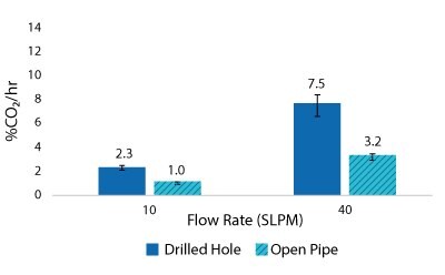
Figure 5.2000 L Spargers CO2 Removal Rate 2000 L, 20 W/m3, 1XPBS 4 g/L EMPROVE® 188 Poloxamer, 50-100 ppm Antifoam C
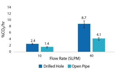
Figure 6.2000 L Spargers CO2 Removal Rate 2000 L, 100 W/m3, 1XPBS 4 g/L EMPROVE® 188 Poloxamer, 50-100 ppm Antifoam C
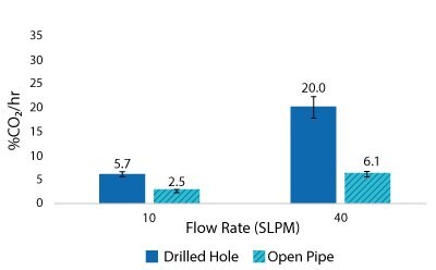
Figure 7.2000 L Spargers CO2 Removal Rate 400 L, 20 W/m3, 1XPBS 4 g/L EMPROVE® 188 Poloxamer, 50-100 ppm Antifoam C
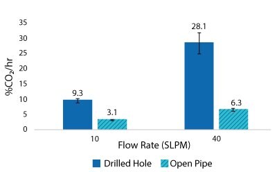
Figure 8.2000 L Spargers CO2 Removal Rate 400 L, 100 W/m3, 1XPBS 4 g/L EMPROVE® 188 Poloxamer, 50-100 ppm Antifoam C
Mobius® iFlex Bioreactors Support a Range of Biomanufacturing Processes
As shown by these highlights from the Mobius® iFlex Bioreactors Scalability and Performance Guide, this portfolio of bioreactors offer the performance capabilities to support a range of biomanufacturing processes. The systems can support the demands of higher cell densities while remaining flexible and scalable from 50 L to 2000 L. Physical properties such as mixing time, volumetric mass transfer capabilities and power input ensure the bioreactors can accurately and effectively control critical process parameters.
Component durability and duration testing results, which can be found in the full-length performance guide, confirm the design of these bioreactors are robust and capable of supporting performance targets over the course of the bioprocess.
To continue reading please sign in or create an account.
Don't Have An Account?